Therefore the radiation resistance of a fractal loop antenna is lower than that of the corresponding simple loop antenna. The half-wave dipole also called a doublet is.
Top Band Hams Vertical Loop Antennas
Polarized radiation could be emitted at some intermediate direction by a system of electric dipole antennas all close to the ground plane.

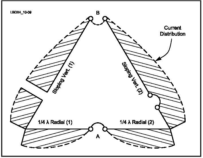
. Polarization of Loop Antennas HF DX signals are constantly changing in polarization The loop may be vertical or horizontal depending on feed point Vertical polarization is preferred when antenna is low DX rule is to feed the loop for low radiation angle Practical consideration is feed at ground level Select Feed Point to keep. Delta Loop Antenna Radiation Patterns. Generally a magnetic loop will have its highest radiation inline with the vertical elements.
H-plane represents the Horizontal pattern whereas V. Note the low angle of radiation. The radiation is verti-cally polarized and peaks in the plane of the loop.
Even though the low angle radiation may not be any better than a dipole an elongated loop narrows the vertical pattern and can reduce the strength of signals coming in at higher angles making it easier to hear the DX. The feedpoint impedance of the 2 wavelength loop is around 260 ohms at the resonant frequency which is a bit lower than twice the fundamental. These resultant patterns are known as Horizontal pattern and Vertical pattern respectively.
In Lecture 16 we showed that an. This is a very realistic situation especially on 80 meters. DX Wire Antennas Comparisons.
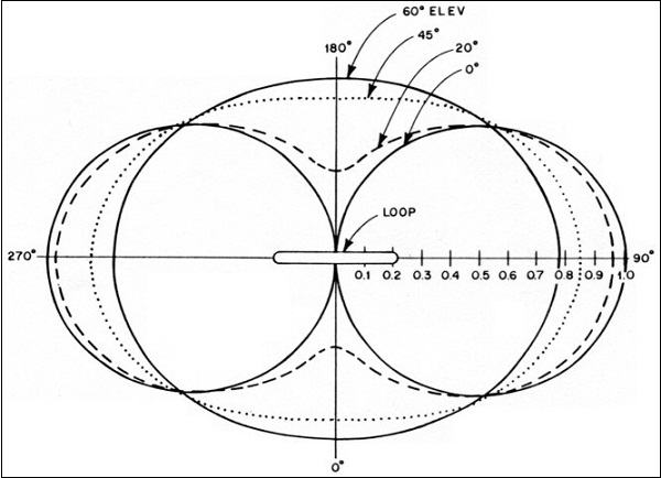
The vertically oriented STL antennas -of-8 doughnut shaped radiation pattern figure maximum is in the plane of the loop with -farfield nulls for small loops at right angles to the plane of the loop. The two above pictures show the radiation pattern of the Delta Loop fed in the bottom corner of the antenna. Figure 1B The far-field radiation pat-tern of a very small vertical loop in the horizontal plane.
When looking through the loop from the side there is a deep null where the signal can be greatly attenuated. Note that the vertical pattern of a dipole changes radically as height is changed above 14 wavelength or 125 feet on 160 meters or 65 feet on 80 meters. Vertical Loop Antenna Polarization.
Left is the 3D pattern. This allows it to obtain the maximum signal for standard VHF omnidirectional radio range localizer VORLOC and area navigation systems installed in lightweight aircraft medium twins and helicopters operating up to 250 miles per hour. The radiation of many antennas shows a pattern of maxima or lobes at various angles separated by nulls angles where the radiation falls to zero.
Two examples of the pattern of the conductor in fractal loop anten-nas. Middle and right show vertical and equatorial slices respectively. Circularly polarized radiation can be emitted in the vertical direction by for example a pair of small loop antennas with common centers and whose loops lie in orthogonal vertical.
The three-dimensional pattern should look like a toy balloon with the filler at the bottom. To make sure this is clear lets review what is plotted. The loop is vertical in free space with the plane of the loop run-ning left-to-right.
For example for the monopole antenna the surface looks like Figure 2. Radiation pattern for a monopole antenna. This null progressively fills in as one makes the loop diameter larger.
Radiation pattern is vertically polarized and with nulls in the broadside directions. Loops can be divided into two general classes those in which both the total conductor length and the maximum linear dimension of a turn are. The base of the Delta Loop is only 10 feet above average ground.
Required NVIS Antenna Vertical Directivity Pattern The vertical or elevation directivity pattern should have a beam width -3dB of approximately 100º and the horizontal or azimuth directivity pattern should be omni- directional. Ad Check out Diamond Antennas 5-Band 40m20m15m10m6m HF Vertical. Vertical antenna meaning that vertically polarized loops close to the ground will not work well over poor soil.
Two-dimensional pattern can be obtained from three-dimensional pattern by dividing it into horizontal and vertical planes. Fig 10-3 shows both the azimuth and elevation radiation patterns of a vertically polarized quad loop with a top height of 03 λ bottom wire at approximately 004. -The wave emitted by the vertical loop may be polarized vertical or horizontal.
This null is very narrow and is. The figures show the Omni directional radiation pattern in H and V planes as explained above. A vertical loop makes a good NVIS antenna for the lower bands even if it isnt very high and feeding it at the bottom reduces the required feedline length.
Loop Antennas 5-1 A loop antenna is a closed-circuit antennathat is one in which a conductor is formed into one or more turns so its two ends are close together. Vertical Delta Loop-Low height and low radiation angle -Portable and compact -No radials -Lower Noise -Essentially a mono-band antenna -Depends on ground quality -Very large on 80m and 160m. The shape of the vertical pattern is a vertical cross cut of the three-dimensional graph.
The 80 meter Delta Loop is mounted in a vertical plane. L3Harris N48 Series balanced loop antenna design assures an omnidirectional radiation pattern at the horizon. The area of a fractal loop antenna is less than that of the geometric flgure on which the fractal loop is based as shown in Fig.
This is because the radio waves emitted by different parts of the antenna typically interfere causing maxima at angles where the radio waves arrive at distant points in phase and zero. Vertical plane loops tend to waste more radiation at high angles when they are 2 wavelengths or longer which limits their application as multiband antennas. By the time the loop.
The horizontal loop vertical pattern stays relatively constant only decreasing in ground loss as height is increased. Measuring Antenna Radiation Patterns Antenna is rotated in an Anechoic Chamber to measure radiation pattern Radiation pattern of any antenna Is the shape of the Electro-magnetic field radiated or Received by the antenna Dipole Antenna One of the most widely used antenna types is the half-wave dipole. This is known as a 3D radiation pattern.
Radiation Pattern in 2D. In the shown polar diagram a quarter part of the circle with the antenna site as the origin the x-axis is the radar range and the y-axis the aims height. Ad Compact system no anechoic chamber needed.

Delta Loop Antenna Radiation Patterns Hy Power Antenna Company
Antenna Theory Loop
All Band Use Of Vertical Plane Deltas

Delta Loop Antenna Radiation Patterns Hy Power Antenna Company

Delta Loop Antenna Radiation Patterns Hy Power Antenna Company

Delta Loop Antenna Radiation Patterns Hy Power Antenna Company
Delta Loop
Radiation Pattern Of The Loop Antenna Download Scientific Diagram
0 comments
Post a Comment